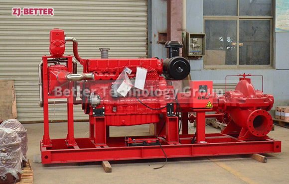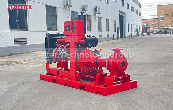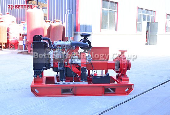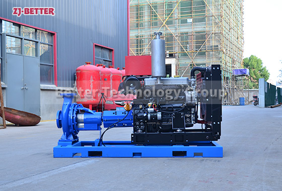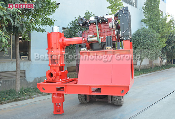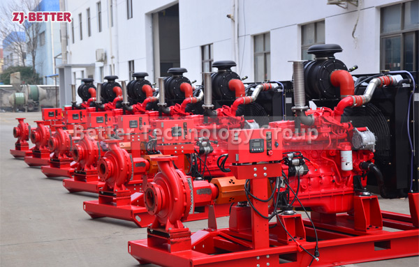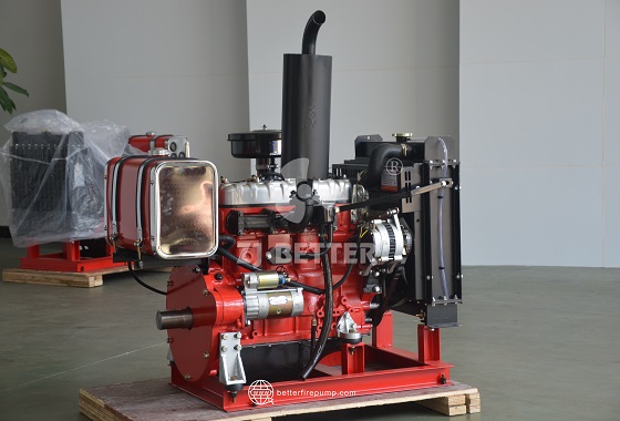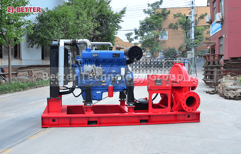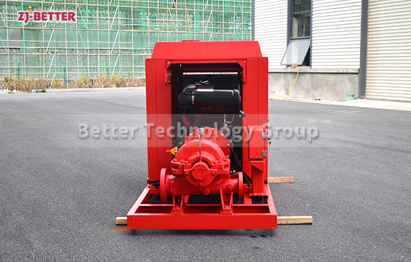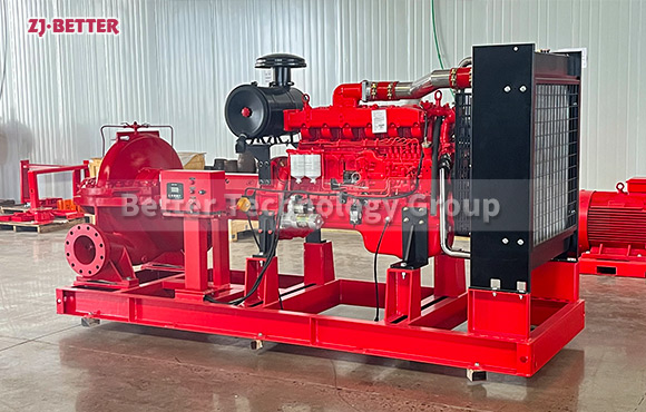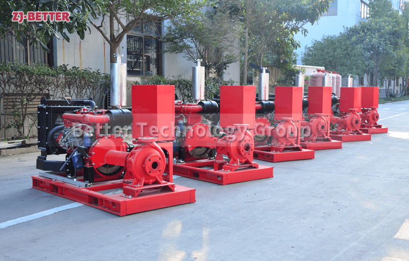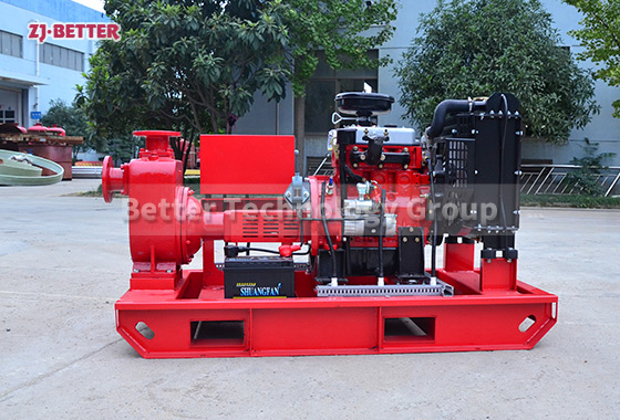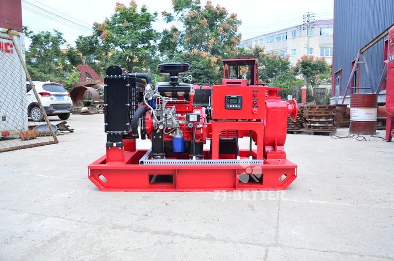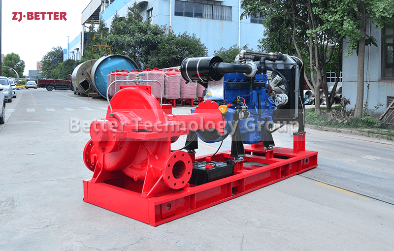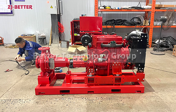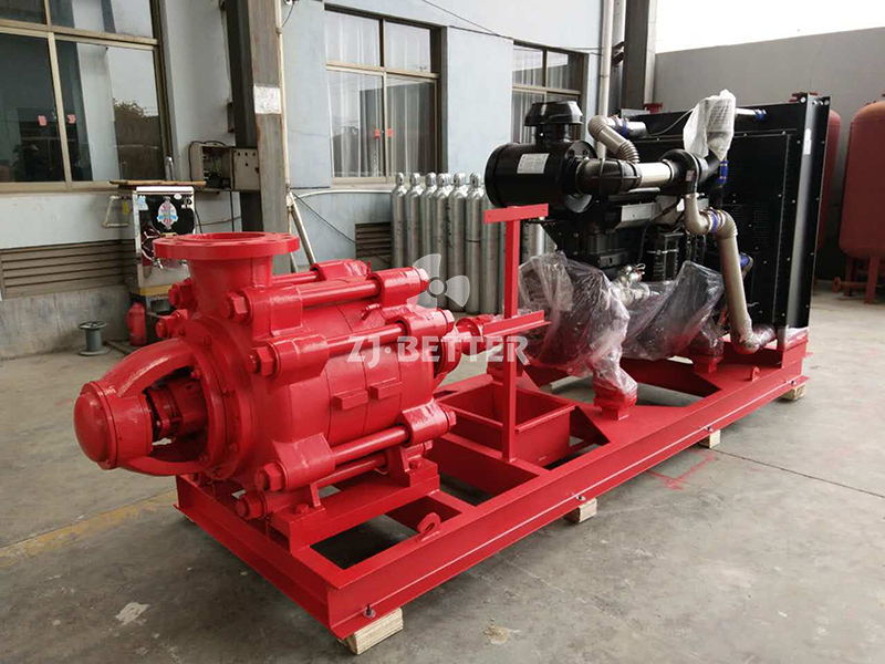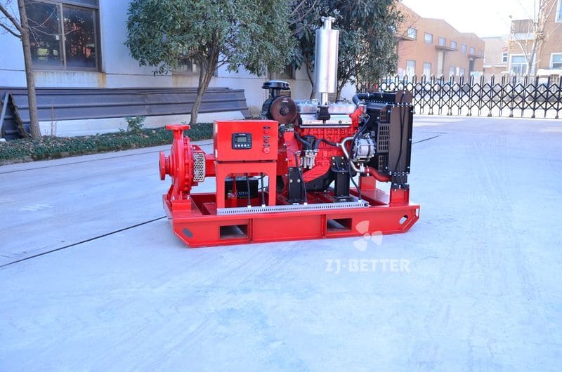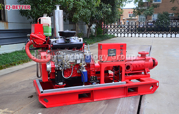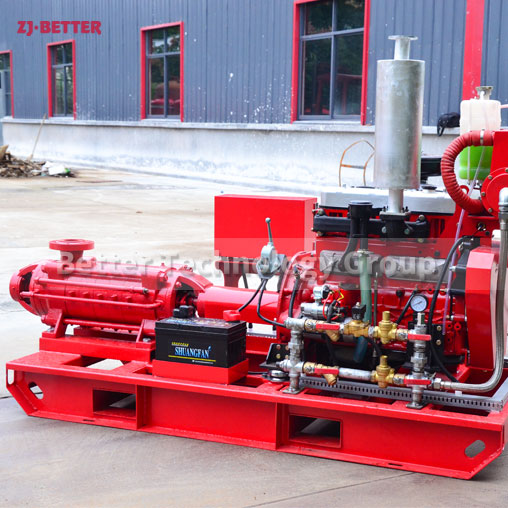
Structure Description of XBC-D Multistage Diesel Fire Pump
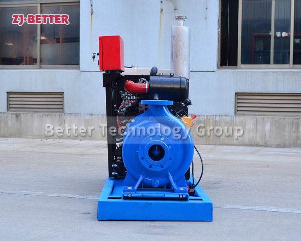
The number of impellers is different, and the head is also different: Generally speaking, a single-stage pump has only one impeller, while a multi-stage pump has two or more impellers, which enables it to suck water many times and segment it. processing, which greatly increases the lift. Therefore, under the same medium flow, the lift of the multi-stage fire pump appears higher.
The basic structure of the multistage pump is composed of the water inlet section, the water outlet section, the middle section, the tail cover, the impeller, the pump body, the pump shaft, the bearing, the sealing ring, the stuffing box and other components.
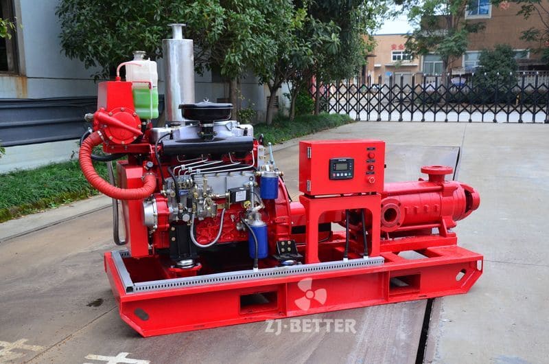
1. The impeller is the core part of the multi-stage pump. It has a high speed and a large output. The blades on the impeller play a major role. The impeller must pass a static balance test before assembly. The inner and outer surfaces on the impeller are required to be smooth to reduce the frictional loss of the water flow.
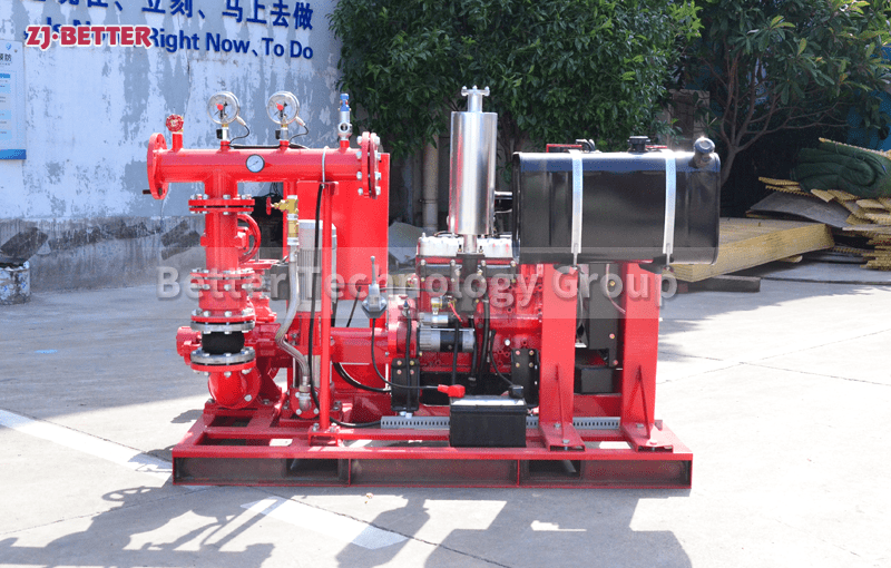
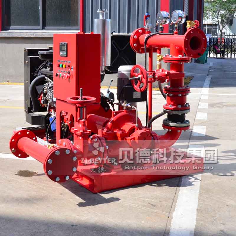
2. The water inlet section, the water outlet section and the middle section are also called pump casings, which are the main body of the multi-stage pump. It plays the role of supporting and fixing, and is connected with the bracket on which the bearing is installed.
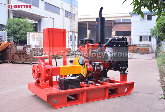
3. The function of the pump shaft is to connect the motor with the coupling and transmit the torque of the motor to the impeller, so it is the main component for transmitting mechanical energy.